Supra Forums banner

Ecu pinout needed!

18K views 25 replies 7 participants last post by  kriss_pl  
#1 ·
Guys, I found two, but none is good:/
I need Ecu pinout for my USDM 95 NA with W58
Help!
 
#6 ·
I'm not sure I believe the pin out from the link above at least for the 2JZ-GE. Being that your car is a 95 USDM 2JZ-GE, W58, pins 1-6 should be empty. If you had an auto transmission, then pin 3 should be the GND signal for the auto transmissions Vehicle Speed Sensor (which you shouldn't have).

Here is what I see as the pins for TPS, RPM, and Speed Sensor:
TPS - Connector E9 (80 pin connector) Pin 43 (Yellow wire)
RPM - Connector E9 (80 pin connector) Pin 27 (Black Wire)
No1 Vehicle Speed Sensor - Connector E10 (40 pin connector) Pin 2 (Pink Wire)

This information can be found here:
http://94supraturbos.synthasite.com/resources/95_TSRM_PDF_FILES/Wiring Diagrams.pdf

Make sure to double check the information I have provided in the link as this is the first time I've looked for this on a 2JZ-GE.

Switched 12V can be found on any power circuit after the ignition switch and ground can be the chassis. What are you trying to connect? If you are connecting an aftermarket electronic box, find a switched 12V power source for a less important circuit than the ECU circuit (example might be the clock).
 
#8 ·
.....
Here is what I see as the pins for TPS, RPM, and Speed Sensor:
TPS - Connector E9 (80 pin connector) Pin 43 (Yellow wire)
RPM - Connector E9 (80 pin connector) Pin 27 (Black Wire)
No1 Vehicle Speed Sensor - Connector E10 (40 pin connector) Pin 2 (Pink Wire)
.....
That's correct there according to my 93 TSRM vol1 and my 93 Supra Electrical Wiring Diagram (has color coded wiring diagram), ^_^
 
#9 ·
Thanks Roy for confirming that.

Don't go off of that diagram as it appears to be incorrect. Your harness is correct. Pins 1-6 and 8-10 are empty, only pin 7 has a wire for Ground on the distributor. This is correct for the W58 transmission. If you had an auto, then pin 3 would be ground for the auto tranny wheel speed sensor and pins 8, 9, 10 would be for the transmission solenoids.

Do you have the instructions for wiring up the AVC-R? Would this help you (only references the 2JZ-GTE though)?
http://www.mkiv.com/techarticles/avc-r/e.htm
 
#11 ·
ECU signal E11 (E9 Pin 4) may just be an unused ECU ground. I can't find its use any where in the tech manuals. ECU Ground can be found under ECU signals E1 (E9 Pin 69), E01 (E9 Pin 80), and E02 (E9 pin 79) so E11 (E9 Pin 4) may just be a redundant ground. This is probably why there is no wire coming out of this pin. Your harness appears to be correct, as is the rest of the diagram on 94supraturbo.
 
#17 ·
E9-pin4 E11 ECM Ground is used in both USDM GE and GTE. 93 TSRM page EG-653(GE) and page EG-807(GTE) for the pin-outs. Page EG-651 Wiring Diagram shows it goes to ground and is used by the 3 O2 to go to ground. 93 Electrical Wiring Diagram Book Page86 Engine Control Diagram shows E9-pin4 goes to "Junction Connector J2" which eventually leads to ground. E9-pin69, 80, 79 goes directly to ground.

T7-D matches with the GE pin out.

^_^
 
#14 · (Edited)
Thanks guys for all the answers! I ve found the link from above, somewhere in google but thought its incorrect to, because of that ground pin.
Tomorrow im going to connect the wiring and check if everything is ok. I will write it here and in my project thread.
Thank you once more;)

P.S. Question not related with problem from above.
I have aftermarket FFIM and oem fuel rail-will aftermarket Top fit injectors feed oem fuel rail with no problem?
 
#16 ·
The pins I gave above were before I new you were installing the AVCR so there might have been some confusion on the wiring. I just looked through the wiring instructions for the AVCR and even though the install is only for a 2JZ-GTE, the pins appear to be the same. The instructions show the following:

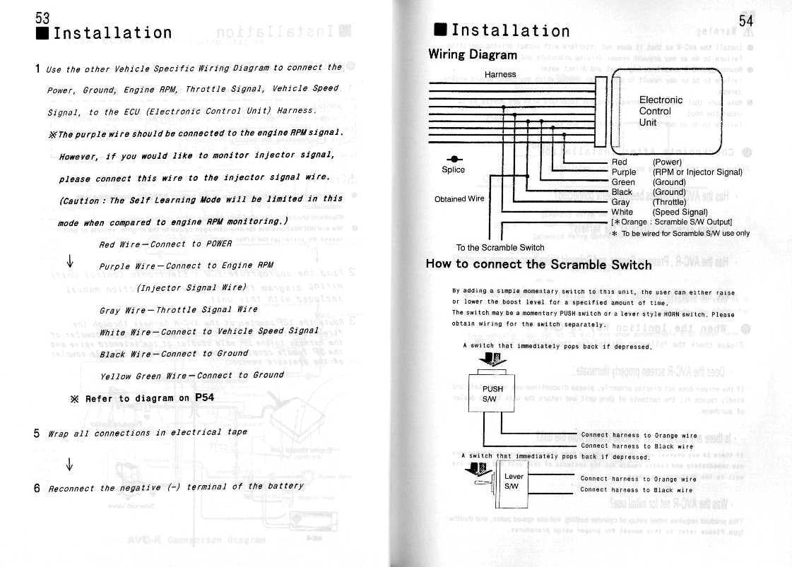
AVCR Red Wire (Power) to E10 Pin 31 Black–Red Wire (Power)
AVCR Purple Wire (RPM) to E9 Pin 58 Red–Yellow Wire (IGF-RPM)
AVCR Green Wire (Ground) to E9 Pin 69 Brown Wire (Ground)
AVCR Black Wire (Ground) to E9 Pin 69 Brown Wire (Ground) - connect about an inch away from the AVCR Green Wire on the same wire
AVCR Gray Wire (Throttle) to E9 Pin 43 Yellow Wire (Throttle)
AVCR White Wire (Speed Signal) to E10 Pin 2 Pink Wire (Speed Signal)

AVCR Wiring
Image


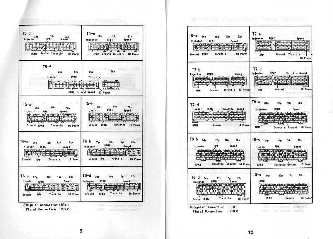
AVCR diagram T7-d for 2JZ-GTE harness
Image


Make sure to go through the Toyota wiring diagram in the TSRM as well as the AVCR instructions to verify all of this as I have not installed one of these before.

Once it's connected correctly, there are some initial settings you'll need to setup in the AVCR. This should be in the instructions as well.
 
#18 ·
Ok. AVCR works, throttle position works ok, speed - dont know yet but something is wrong with RPM. On idle it shows 4500-5000, sometimes 0 - something is wrong with the connector or I dont know how to set something in AVCR. Anybody here with info about that initial mode - how does it work?
 
#22 ·