Supra Forums banner

Oil catch cans - 2022

21K views 55 replies 23 participants last post by  Kingtal0n  
#1 · (Edited)
There's more than enough solid options for catch cans these days so let's not discuss one brand over another. I'm actually wondering why the size of the lines and the volume of a can itself doesn't seem to be discussed, what's the benefit of going bigger or smaller in line sizing and catch can volume? Hoping for some details on what you guys run and why you chose that sizing if possible.

Feel free to debate each others preferences here, I honestly want to learn the ins/outs of a catch can so the more knowledge and experience the better.
 
#2 ·
I installed the radium dual catch can setup because of the quality and I like their press fit fittings that go into factory valve covers. Aside from that I couldn't tell you if it works better then others but it does collect blow by oil and moisture as intended.
 
#7 ·
I have the Radium VTE setup as well, though I did upgrade the exhaust side to AN10 fittings and hose. Also, the fittings into the valve covers are AN10 for the exhaust, and AN6 for the intake. I removed the oem PCV valve, and am using the Radium PCV valve right on the left-side catch-can.

I figure it works as follows ...

Under idle or no-boost the intake chamber is under vacuum. So it draws from the intake valve cover via the PCV valve, but it's not a huge draw. Enough to ensure the crankcase area can't build up pressure. The exhaust side is also pulling.

Under boost the intake-side is out of the equation - the PCV valve is closed so nothing goes through there. The exhaust side however sees a significant vacuum draw from the intake pipe. That with the AN10 sizing ensures that crankcase area doesn't build up pressure.

The catch-cans will do a good job of separating oil from the vapors. Some will get through to the intake, but not enough to worry about. NOTE I say will - I'm still working on the VVTi head and going-single conversion. If it looks like too much oil going through, I have information on using proper air-oil separators


Radium makes (as usual) a gorgeous one

IAG makes them, but they're kind of big - this is used to demo in the video above

And BMW has one, but ugh, plastic
 
#8 ·
Awesome, that IAG setup looks like the ideal setup but, might be a bit overkill/over sized for fitting next to the ABS pump. I had my eye on the Radium kit since its more compact and their HQ is like 15 mins from me but their kit brings up my main question. They list about 45 different fittings all in 10AN in the drop down menu with numerous different barb sizes. Why choose one over the other and not simply offer 1 size? What's optimal for say 500hp, or 1200 hp, or 15psi or 40 psi?

For the actual separator/catch can volume, I think I've determined the chosen volume of the can is solely based on preference and/or how often you want to drain it, amount of blow-by for your build, fitment etc. No actual performance or mechanical benefits either way. AKA, to clean up clutter, probably smaller the better as long as it's functional.

For line sizing, I'm hearing bigger is better but, most everyone rolls with 10AN or more serious power I'm seeing even 12AN. Would it not function as efficient with smaller 6AN or 8AN lines? Simply comparing to the factory PCV sizing, I would assume 10AN's a good place to start.

I feel like I'm just overthinking this haha
 
#11 ·
I went with 10AN as radium offers the off-the-shelf press-fit banjo fittings for the valve covers. I am sticking to -10AN sizing as I am running <30psi and will be pulling vacuum from the exhaust using one exhaust evac fitting per valve cover -10AN all the way.

Before people start talking about one-way valve failure with these setups, I have PTFE one-way valves installed midway through the line from valve cover to exhaust so that they one-way valves experiences only engine bay temperature, not direct exhaust heat.

I chose no catch can due to simplicity and weight. -10AN as it was readily available off the shelf for both the evac and valve cover fittings, and should both flow enough air and pull enough vacuum for my boost pressures.

Hope that helps.
 
#12 ·
Ah, I've been wanting to hear from someone with experience on the exhaust vacuum route. I assume the amount of vapors and oil pulled from the valve covers are so minimal, you don't notice any more soot, smoke or fumes than usual? If you're running a catalytic converter, is your connection before or after it? Happen to have any pictures of where/how its connected?

Coincidentally, I was looking around at some builds on my lunch and came across a set of GTE valve covers with 12AN fittings welded in, too good of a deal to pass up in todays parts prices. Looks like I'll be running 12an lines, further research be damned haha
 
#14 ·
I am going for more a drag specific version. If you look at most drag cars they have their catch can/ breather/ puke tank located in the rear of the car. This way during a pass if you have a bunch of blow by and it ends up filling the can and spits up oil, it doesn't spit out in front of the tires which could cause a crash and be a very bad day. There is also a 2nd reason to have the catch can located in the rear of the car. Which is; you need to cool the blow by gasses in order for them to condense and actually get caught in the catch can. When your catch can is in the engine bay like most all of them are, you don't have enough temp difference from the valve covers to the catch can to condense the vapors. Then you are essentially venting 95% of that vapor to atmosphere or back into the intake track and right through the turbo. The long distance the vapors have to travel from the valve covers to the rear of the car will allow the vapor to cool and condense in the can.

What i am doing right now is i have a -10an 90* coming off each valve cover like most all of us do and then i got 2x -10an lines going in to the trans tunnel to a Tee under the car which is 2x -10an to 1x -16an line. I'm running the lines under the car on the passenger side, up over the rear subframe into the rear bumper.

Id post some pics but this site makes its kind of a PITA but you get the idea.... 2x -10an tee'd to a -16 line that goes to the rear bumper all under the car on passenger side.
 
#15 ·
For the guys with the Radium VTA, do you get fumes coming into the cabin?
 
#17 ·
Yes if the AC is set to outside air and I'm in slow traffic, no when it's set to recirc. E85 doesn't smell as bad as straight gasoline, either.
 
#18 ·
with the radium dual VTE setup, since it’s a closed system wouldn’t any potential oil condensation end up in the can anyway ? ideally I wouldn’t like to increase any gas/e85 smell.

i still have my charcoal canister/no cats and would mount the twin catch cans on either side of the engine with the provided brackets (instead of both together in the charcoal canister location, they provide all 3 brackets). as it is now, i get no fuel smell in the cabin.
 
#19 ·
Mark, you won't smell anything with the VTE configuration.
 
  • Like
Reactions: Mark 2JZ
#20 ·
From experience a fuel smell is from not running a carbon canister or cheap fuel lines, a fuel exhaust smell is from no cats, i have had plenty of cars with open crankcases and never smelled fuel from it. I would think neither the VTA or VTE would cause a fuel smell unless you had fuel in your crankcase (shouldnt). Again i havent purchased a radium kit yet so dont listen to me.
 
#22 ·
It's the blowby vapor one smells, not raw fuel, I wasn't clear.
 
  • Like
Reactions: FastTurbo
#28 ·
Catch can when you want to stop putting oil vapor back into your intake and would like to have difficulty passing emission tests. Cooler when you want to start taking it on extended track sessions. :)

What's a safe size for a catch can reservoir for a street car? .5 liter? 1 liter? bigger?
Size of the can doesn't matter as much as making sure you check it once in a while to make sure accumulation is kept up with. :)
 
#31 ·
We’ll see how it goes. Current blow by is minimal, never had to empty the catch can, it had a maybe 10mL after a summer of driving.

With the added vacuum it may pull more as the old setup vented to atmosphere. There are no sensors downstream of the evac system so I don’t mind if the exhaust gets dirtier inside. Being so close to the turbo my hope is the Vapors are combusted.
 
#33 ·
The OEM factory PCV system is extremely robust and welcome at 1200rwhp for 20 years.

The goal of PCV is to maintain a crankcase pressure below atmospheric at all times. Target publish pressure from factory is 0.5" to 1" Hg
Image


Performance engines prefer more vacuum to control oil. A vacuum pump is ideal because it can be adjusted to desired crankcase pressure.
In wet sump applications it is typical to run 4" to 6" Hg crankcase and some go even further. It depends on the engine.

Vacuum pumps and Dry sump are the epitome of oil control. The crankcase pressure has a direct influence on oil leaking, oil blowing, oil aspiration, oil control.
Thus, you must measure crankcase pressure and control it.

Image


Most people do not even realize they can measure the crankcase pressure or that it has a powerful influence on oil control and oil quality.
Combustion byproducts are dangerous for the crankcase, dangerous for engine oil, they need to be removed quickly, rapidly, by vacuum / suction.
Image


Image


Piston ring function depends on crankcase pressure control systems, piston rings will not seal well if there is pressure in the crankcase, it tries to unseat the ring early causing ring flutter and excess blow-by which contaminates the ring pack and combustion chamber with oil, leading to sticky/stuck rings that no longer rotate properly and increasing blow-by.

Image


This is from a vaucum pump article sort of summarize some of the crankcase pressure control theory
Image


I don't recommend a vacuum pump because it is extra complexity and maintenance. Nevertheless we must control crankcase pressure somehow without one.
Luckily the turbo can act as a vacuum pump to drive PCV. This is how the factory PCV works, utilizing the air filter pressure drop
Image


As the filter is high quality factory paper it quickly builds a pressure drop post air filter, between the turbo and intake filter. That is where the crankcase vent occurs; Thus, at WOT the pressure of the crankcase is pulled down to the pre-compressor wheel pressure ratio.
Here are some practical examples from recent setups
Image

Image


You want Short as possible hose from intake tube to valve cover. You do not want an excess volume, catch can, or large lines, for many reasons.
1. Adding volume to crankcase will reduce PCV pressure signal (there will be less vacuum to go around)
2. Adding lines/hoses will increase friction due to shear stress of fluids which further reduces the PCV pressure signal, raising crankcase pressure
3. Using smaller diameter hoses will maintain gas velocity, organizational flow, heat energy, and prevent condensation, prevent collection of liquid in the tube or intake tract

Summary part 1:
A. you must measure and control crankcase pressure somehow or oil will blow out of the engine, causing oil leaks and oil aspiration issues
B. The intake air filter tract provides crankcase pressure drop during WOT, so proper filtering and crankcase connection here is required if you do not have a vacuum pump or other source
C. The PCV system should be able to rapidly remove combustion gas from the crankcase, with high temperature and velocity, and direct it quickly back to the intake manifold before it can lose energy and condense.

There is a part 2 and part 3 but lets get through this part first, ask ur questions and we go from there
 
#35 ·
The OEM factory PCV system is extremely robust and welcome at 1200rwhp for 20 years.
I have a custom intake plenum, is it as simple as welding a port to it then, oem pcv valve to hose barb on intake manifold ? and passenger side valve cover to one of my twins’ intake tubes ?

From what you’re saying it should be fine with oem hose size as well ? I don’t mind adding that to my setup but all I’m trying to do is lessen oil buildup in the intercooler piping, plenum, etc
 
#34 ·
@Kingtal0n Dry sump user here, as well as someone who hates leaks. My engine has always had an oil leak, and I suspect I know where it is coming from, but I appreciate that you've given me something to consider.
 
#36 ·
Dry sump

If the system cannot pull vac in the crankcase, then that is inadequacies with the scavenge pump system in use. Not any filter valves used, or boost, or rings, or anything like that.
The pump is either capable or it is not...design it right from the outset.
Some dry sump incorporate vacuum pumps as well in pursuit of total oil control.

I have a custom intake plenum, is it as simple as welding a port to it then, oem pcv valve to hose barb on intake manifold ? and passenger side valve cover to one of my twins’ intake tubes ?

From what you’re saying it should be fine with oem hose size as well ? I don’t mind adding that to my setup but all I’m trying to do is lessen oil buildup in the intercooler piping, plenum, etc
Twins, you have OEM twins? The OEM pcv system is already connected to the twins intake tubes. I am not sure exactly what you mean, did you change turbos and ditch the OEM intake tube? Or replace the intake tubes with custom fab work? In any case, yes simply copy the OEM pcv route valve cover -> Pre-compressor intake tube, post air filter.

Lets discuss the PCV valve side now:
Intake plenum -> Supra TT Pcv valve -> Valve cover (crankcase)
This is the idle/cruise side of PCV. This is the lowest flow side, the weak flow side, the high vacuum side, the minimum blow-by condition is idle/cruise.
Therefore no oil should ever be able to make it to this side. The intake should always remain free from oil due to pcv valve -> plenum because its the calm condition flow side, the idle/cruise is very little blow by , very little influence on crankcase pressure.

In other words, typical OEM valve cover baffle prevents oil from getting to the pcv valve, prevent oil ingestion. We see all engines whether turbo or not incorporate some kind of oil baffle system tied to their pcv valves.

So , how does oil still get through sometimes?
High crankcase pressure during WOT forces oil into the baffle:
In the early 2000's I tuned a bunch of 3L and 2.6L Supra/Skyline engines 600-800rwhp that all used catch cans extensively and atmospheric venting, it works well for about 15,000 to 25,000 miles or so, and then the engines begin to noticeably smoke at idle, their intake coating with oil despite the catch cans, the oil leaking develops at the front and rear main seals, the combustion chamber carbon coating seems excessive and piston rings accumulate sticky oil crust, burning remnants of long chain hydrocarbons that used to be quality engine oil, taken all together the engine compression is often hampered by valves that stick or piston rings that no longer function well. We had alot of engines that needed to come apart for cleaning, soaking in powerful solvents to remove carbon buildup from valves/head/rings. The amount of oil blowing out of the engine seems to increase over time as well, as baffle systems begin to fill with oil, when the engine goes WOT more oil blows into the baffle and into the can. Oil cannot easily get out of the baffle once its past a certain point, the baffle acts like a kind of 'can' itself. Alot of people don't realize that pcv valves leak briefly before closing and also a small amount even when fully closed, and this seems to contribute to baffle oil accumulation in the valve covers which is later sucked into the engine during high vacuum condition through the pcv valve even though the oil was originally forced into the baffle at WOT. The fix of course is crankcase pressure management, fixes everything except the cleanliness, for that you need both pcv AND a superior filtration quality, together enable high mileage for typical engines.


From what you’re saying it should be fine with oem hose size as well ? I don’t mind adding that to my setup but all I’m trying to do is lessen oil buildup in the intercooler piping, plenum, etc
Now lets tackle WOT side
Hose sizing on WOT side (non PCV valve side) is related to the blow-by and engine conditions, racing concerns, external forces
Ex. If there are enormous ring gaps, 1500 horsepower, or if the vehicle is 'thrashed' high cornering forces or possibly going upside down or something,
Then you may want larger diameter tubes, to help prevent oil clogging, control oil flow that manages to bypass the OEM baffle, and deal with high flow volume, hell you may even need to add an external reservoir which is connected back to the oil pan (A 'catch can' that doesn't catch anything) Exactly on the sr20det models which incorporate a return path for oil leaving the valve cover baffle.

But that is extremely rare situations. Most of us drive on the street or quarter mile the car, not really thrashing or 1500hp for extended periods stuff. Power doesn't cause the excess pressure by itself, its the blow-by that causes pressure, blow-by based on ring and cylinder wall setup. E.g. you can buy low tension oil rings that require a low crankcase pressure driven by a vacuum pump. Those ring will not work at typical OEM crankcase pressure levels, it will gush oil from the crankcase. Not a one-size-fits-all solution for this, just match your application to the setup as with anything else.

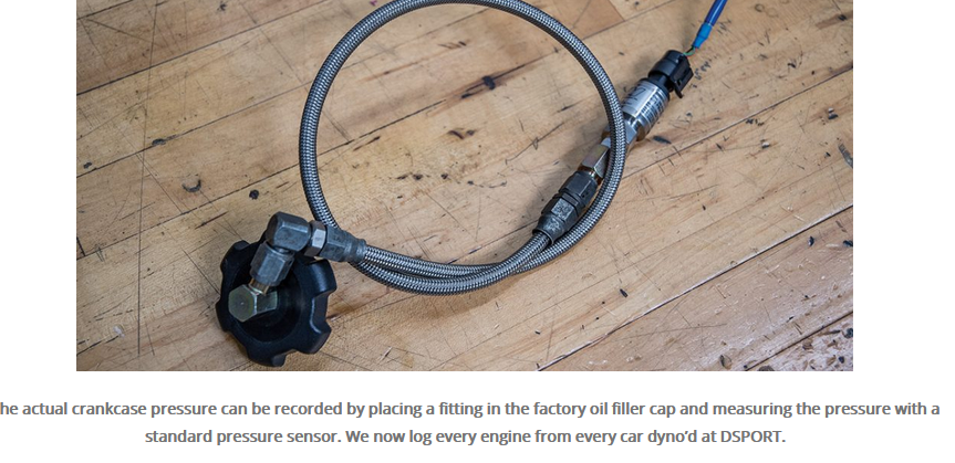
The important thing is no matter what size hose you choose to use, measure the crankcase pressure and adjust as needed. Large hoses may slow the eventual depression of crankcase at WOT, or if the pressure drop is minimal from the filter it may even allow the pressure of crankcase to rise slightly. Which you will notice on the data-log and make adjustments as needed to fix the rising crankcase pressure before it can have adverse affects.


Back to Idle/cruise Intake PCV valve suction side discussion

For the intake manifold side, (plenum -> pcv valve -> crankcase) the size of the hose can remain small:
The intake suction is very high at idle/cruise on most engines, and the PCV valve orifice for wet sump OEM is very small and controlled nozzle design, and the hose is typically small diameter and very short. Thus if you change the cam for example, 18" at idle vacuum to say 12" at idle vacuum, its still alot more vacuum than needed for PCV at idle/cruise (around 2" Hg only is needed). Therefore adding volume of a can or larger lines to this side of the PCV system will not have any affect on the crankcase pressure, but it WILL slow down the pressure drop during transitions between throttle positions due to additional volume (constant flow rate from a specific volume = slower change in pressure given a new larger volume with the same old flow rate)

That said, no healthy engine should ever need a catch can on that side of the engine, because the intake manifold suction is only applied during idle/cruise states where the rate of blow-by gas and whirlwind/hurricane influence of rotating internals is minimized during those conditions.
In other words, for oil to blow out into the intake manifold on a wet sump application through the PCV valve, it means the oil baffle has already previously been filled with engine oil due to high crankcase pressure at WOT which has nothing to do with this side of the PCV system or anything after the pcv valve which slams shut at WOT.

To put it another way, oil blows out when crankcase pressure rises dramatically due to uncontrolled blow by -> Which happens at WOT, not IDLE or CRUISE. The idle/cruise conditions is the 'gentle' internal environment and 'minimum' blow by condition, very unlikely to send oil out of the engine. If the engine oil baffle is continually filling with engine oil at WOT it will eventually become so full of engine oil that the pcv valve will literally be swimming in oil, and have no choice but to pull oil into the intake manifold, like a straw stuck down into a cup just able to reach the liquid.
Whereas if the engine was healthy and the crankcase pressure was controlled properly the engine oil control baffles (in the valve cover on wet sump) would never fill with oil in the first place, so you would never see oil flow towards the intake manifold because the baffle would not be able to fill with oil and due to it's design (all cars, all valve cover baffle systems) is specifically designed to prevent oil from reaching the pcv valve when crankcase conditions are as measured by the OEM engineers on the OEM pcv system. Which is why they designed it like that in the first place. I guess.
 
#37 ·
Sorry I know I write alot i Just want everyone to save time and money and understand this basic thing

If I were to summarize everything in part1 down to a single sentence:
"Measure the crankcase pressure of a completely original turbo engine (Toyota/Nissan/Subaru/etc) And then adjust your heavily modified, high output engine to match those OEM crankcase pressure levels, and it will solve/cure all oil related aspiration/leaking/blowing issues related to blow by gas(maybe not high G cornering/thrashing though), as blow by gas provides energy to force oil from the engine and facilitates larger more frequent oil droplet formation, it must be controlled to prevent that from happening"

And as sort of an additional detail, "Maintain OEM air filter quality or better in conjunction with OEM crankcase pressure levels to enable high mileage, as it takes both together to maintain oil quality" In other words, preventing oil from blowing out of the engine isn't enough to protect the engine oil and crankcase from sludge and carbon buildup, you also need to heavily filter the air entering the crankcase and engine combustion chambers to fully protect the oil seals and prevent conglomerate formation"

In part 2 or 3 I will discuss the size and shape of oil molecules as well as the air particulate sizes and quality, and we will observe constituents of normal air which are dangerous to the crankcase and facilitate creation of carbon conglomerates. Its just organic chemistry.
 
#39 ·
Here is an example measurement taken between filter and compressor wheel, I got this from a published paper it is not my data
Image


I shoot for at least 10 to 15" Water in the crankcase if possible, which may take 15" to 20" of water at the turbo inlet, which is about 0.7psi of pressure drop, completely reasonable for a high quality air filter. It is easy to get lucky and find a random filter with that property.


However, for cleaner engines use more pressure drop. I like to add pressure drop using idle/cruise PCV circuit and let WOT stay near -0.5psi only for short durations. Some OEM turbo engines like RB and SR use vent restrictors to achieve this affect, heres one from an RB
Image

This OEM restrictor causes crankcase pressure at idle/cruise to be much lower on those turbo engines. I'm not sure I've ever seen one of these on a 2jz-gte though. I actually learned about these restrictors kind of after the decade of installing and tuning 2jz engines so I never really 'looked' for one until they were basically antiques and dissipated.
Anyways. You fashion a restrictor like this and drill the hole to suit your crankcase pressure desires- If you want 3" of vacuum it may take a 10mm hole but if you wanted 1"Hg maybe 12mm diameter hole instead
I have picture for the V8 but its the same application principle
Image

Notice the air gets whipped into the crankcase, crosses over to the other side of the engine, to the other valve cover, and exits. This sort of flow through strategy is necessary because of the way molecules push and shove each other energetically, mean free path is small, gas density is significant, its just the best way to control the flow and contents of the crankcase.
 
#40 ·
Excellent posts by @Kingtal0n

I've touched base with this on Rotary motor builds with Rob at Pineapple racing, and one advantages of those engines actually have over piston engines, is that is has less windage, so it was also about properly sizing the ventilation, and it wasn't another "Bigger is better" kind of cases.

Hence, huge ventilation hoses in those kind of builds are pretty rare, as there is such thing as excessive vacuum, and why also the OEM don't run huge hoses in factory cars, and in some cases, even run with restrictors as @Kingtal0n has mentioned.

We talked about adding restrictors in the vacuum inlet if there was excessive amounts of oil build up in the intake tube, but running a crank case pressure sensor and sizing the setup to maintaining the levels close to atmospheric threshold under a wide range of varying loads would be ideal.

PHR has released these a little while ago, so it'll be cool to see some more data on crank case pressure of varying different HP down the road.

I'll be intrigued to see if majority of the FMS issues here, are actually caused solely by crankcase issues, installation or a combination of both, since installing the seals flush in our oil pumps actually blocks off a part of the oil drain hole behind the seal, causing a drain back problem that builds up oil behind the seal that'll eventually push it out.

 
#41 ·
Part2 'catch up'
Everybody's favorite topic: air filtration
Then compares oil molecule size with dust and debris. Finally discuss impact of fungus and pollen and elements of water injection, calculate temp drop due to meth spray on paper.

When I say cast, I mean brittle materials as opposed to ductile. There are only those two types, brittle or ductile. Hyper pistons are brittle, and feature low expansion coefficient, so I consider them as cast pistons.
The cast piston checklist applies to all engines, any engine. But if the piston is forged it can tolerate a much higher temperature and it also must warm up before it can expand fully in the bore which can take 20 to 40 minutes. Cold starts are the bane of forged internals, the most wear and tear. A cast piston engine can be in boost almost immediately after it is started in comparison due to tight cylinder wall clearance when cool still.
The cast piston is not the weakest link in terms of power output of most OEM engines. There are many ways to protect them from harm while making enough power to deform connecting rods, which by far seem to be the limiting factor when it comes to squeezing turbo induced potential from any engine, as the crank and pistons tend to be sometimes twice or more as capable. Stuff like filtration seems trivial because air is invisible i guess... but once you realize what is in the air that you don't see, the size and quantity of things such as pollen and fungus, and there is much more, and then calculate how much air moves through an engine per second or minute or whatever... those microscopic things start adding up quickly. Millions becomes billions trillions etc... and they are enormous compared to oil molecules... its like giant buildings raining down on a pile of leaves. Big disruption to the oil film in millions of locations in short time, ruining the piston ring seal little by little, getting caught between ring and sticking to the ring, preventing a complete seal that would have been possible. And the sheer quantity of trapped particulate, much of which has been smashed and burnt so its all disorganized carbon oxygen and nitrogen radicals obfuscated, sticky tar like seems the most common deposit formation after traveling along in engine oil some ways, you might call it 'atherosclerosis' of the oil system. Please understand I am summarizing these details, this is the short version, there is a book of writing involved in explaining every part of a single cell and how many of each thing there is. And that is just barely scratching the surface of air contents, there are so many other types of debris to consider. It isn't worth getting into; just filter the air properly and forget about it.
Most pistons are easy to break at high output if you do not pay attention to the variables listed and part of it is keeping the ring seal free from debris which involves superior filtration no matter how much power you want to make.

Next
Review pressure drop, oil leaks due to pressure, engine baffle, gas velocity & separation, contains Dsport article, and gas kinetics

It doesn't matter how you get the vacuum into the crankcase. A vacuum pump is great, but complexity, cost, maintenance are not favorable in daily driver apps. So we usually find other ways to generate a vacuum. Turbo can drive a suction using the air filter. There are also exhaust driven styles which sometimes work well, but I don't see much success using those on turbo downpipes where it is common to have a too-small of downpipe and exhaust gas pressure prevents PCV from working optimally.

Next there are electric pumps found on all kinds of different cars for various reasons. Sometimes people like to use these for crankcase vacuum, I've never done it but it seems pretty simple compared to the belt driven version and if it works it works right?

Here is an example of somebody using electric pump for PCV in crankcase pressure monitoring and control
BW S362 SXE TwinScroll Project - EvolutionM - Mitsubishi Lancer and Lancer Evolution Community
Upon inspecting the 15amp fuse it had blown so it was not working when under boost. This might explain why I had oil pushing past the rear main seal. I swapped in a 20amp fuse and it works like it should and pulls ~5" at idle. Because I monitor the pressure with my AeroForce Gauge it allows me to set a warning light. I now have the warning light come on anytime the PCV presssure exceeds 0psi.
I hope this example helps put PCV into perspective. You must control the pressure somehow, electric pump, belt driven, exhaust driven, turbo driven, find some way to achieve the goal of low pressure in the crankcase.